Follow Me

Dropbox. ?Spread the word.  The first 2GB is free!

Journal Index

Entries in 3ds max (20)

Monday
Aug222011

Sellwood Bridge Collapse

I took some redcam footage of the sellwood bridge fromt he east side, and I removed most of the bridge so i could have it collapse, caused by an inial explosion at the concrete pilon.  here are a couple of the tests.

First test where everything just falls all at once.

Here I've now got things timed out, but I need to remove the bounciness of the bridge and make it fall apart more.

 Worked on the sim more and started working with Fume to see what I get. A good start, but much more work is needed.

Thursday
Jul142011

Search Engine Queries Summary

I looked at what people are searching for when they end up at my blog and I found one of todays top search terms to be insightful.

I think it was this guy I work with.  I could see him typing that in his browser.

Monday
Mar142011

Making Mirrored Ball and Panoramic HDR Images - Part 1

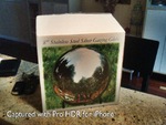
 If your looking for a cheap mirrored ball you can buy an 8" Stainless Steel Gazing Ball here at Amazon.com for about $22. They also have smaller 6 " Silver Gazing Globe  for about $14. It can easily be drilled and mounted to pipe or dowel so that it can be clamped to a c stand otr a tripod.

First, Im no Paul Debevec.  Im not even smart enough to be his retarted intern. But I thought I'd share my technique for making HDRI's. My point being, I might not be getting this all 100% correct, but I like my results.  Please don't get all over my shit if I say something a little off.  Matter of fact, if you find a better way to do something, please let me know.  I write this to share with the CG community and I would hope that people will share back with constructive criticism. 

First, let's start by clearing something up.  HDRIs are like ATMs.   You don't have an ATM machine.  That would be an Automatic Teller Machine Machine (ATMM?)  See, there's two machines in that sentence now.  The same is true of an HDRI.  You can't have an HDRI Image.  That would be an High Dynamic Range Image Image.   But you can have an HDR image.  Or many HDRIs. If your gonna talk like a geek, at least respect the acronym.

I use the mirrored ball technique and a panoramic technique for capturing HDRI's. Which one really depends on the situation and the equiptment you have. Mirrored balls are a great HDR tool, but a panoramic hdr is that much better since it captures all 360 degress of the lighting.  However panoramic lens and mounts aren't cheap, and mirrored balls are very cheap.

Shooting Mirrored Ball Images

I've been shooting mirrored balls for many years now.  Mirrored balls work pretty damn good for capturing much of a scene's lighting.  Many times on a set, all the lights are comming from behind the camera, and the mirrored ball will capture these lights nicely. Where a mirrored ball starts to break down is when lighting is comming from behind the subject.  It will capture some lights behind the ball, but since that light is only showing up in the very deformed edges of the mirrored ball, it's not gonna be that acurate for doing good rim lighting.

However, mirrored balls are cheap and easily available.  You can get a garden gazing ball, or just a chrome christmas ornament and start taking HDR images today.  Our smallest mirrored ball is one othe those chinese meditation balls with the bells in it. (You can get all zen playing with your HDRI balls.)

  • The Size of Your Balls

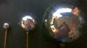
My balls are different sizes, (Isn't everyones?) and I have 3.  I use several different sizes depending on the situation.  I have a 12" ball for large set live action shoots, and a 1.5" ball for very small miniatures. With small stop motion sets, there isn't alot of room to work. The small 1.5" ball works great for that reason.  I'll usually clamp it to a C-stand and hand it out over the set where the character will be.  I also have a 4" ball that i can use for larger miniatures, or smaller live sets.

  • Taking the Photos

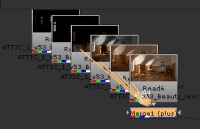
With eveything set up like we've mentioned, I like to find the darkest exposure I can and expose it all the way up to being blown out.  I often skip 2-3 exposure brackets in between shots to keep the number of files down.  You can make an HDRI from only 3 exposures, but I like to get anywhere from 5-8 different exposures.

  • Chrome Ball Location

When shooting a mirrored ball, shoot the ball as close to where the CG subject will be.  Don't freak out about it if you can't get exactly where the CG will be, but try to get it as close as you can. If the CG subject will move around a lot in the shot, than place the ball in an average position. 

  • Camera Placement

Shoot the ball from the movie plate camera angle.  Meaning set up your mirrored ball camera where the original plate camera was.  This way, you'll always know that the HDRI will align to the back plate.  Usually, on set, they will start moving the main camera out of the way as soon as the shot is done.  I've learned to ask the lights to be left on for 3 minutes. (5 min sounds too long on a live set, I love asking for 3 minutes since it sounds like less.) Take your mirrored ball photos right after the shot is done.  Make nice nice with the director of photography on set.  Tell him how great it looks and that you really hope to capture all the lighting that's been done.

  • Don't Worry About...

Don't get caught up with little scratches being on your ball. They won't show up in your final image.  Also don't worry about your own reflection being in the ball. You give off so little bounce light you won't even register in the final scene.  (Unless your blocking a major light on the set from the ball.)

  • File Format

We use a Nikon D90 as our HDR camera. It saves raw NEF files and JPG files simultaneously which I use sort of as thumbnail images of the raw files.  I'm on the fence about using raw NEF files over the JPG's since you end up blending 6-8 of them together.  I wonder if it really matters to use the raw files, but I always use them just in case it does really matter.

  • Processing

To process your mirrored ball HDR image, you can use a bunch of dirrerent programs, but I just stick wtih any recent version of Photoshop.  I'm not holding your hand on this step.  Photoshop and Bridge have an automated tool for proceesing files to make an HDR.  Follow those procedures and you'l be fine. You could also use HDR Shop 1.0 to make your HDR images.  It's still out there for free and is a very useful tool.  I talk about it later when making the panoramic HDRI's.

Shooting Panoramic Images

The other technique is the panoramic HDRI. This is a little more involved and requires some equiptment.  With this method, I shoot 360 degrees from the CG subject's location with a fish-eye lens, and use that to get a cylindrical panoramic view of the scene. With this set up you get a more complete picture of the lighting since you can now see 360 degrees without major distortions.   However, it's not practicle to put a big panoramic swivel head on a miniature set.  I usually use small meditation balls for that.  Panoramic HDRI's are better for live action locations where you have the room for the tripod and spherical mount.  To make a full panoramic image you'll need two things.  A fisheye lens and a swivel mount.

  • The Lens

First, you'll need something that can take a very wide angle image. For this I use the Sigma 4.5mm f/2.8 EX DC HSM Circular Fisheye Lens for Nikon Digital SLR Cameras  ($899)  Images taken with this lens will be small and round and capture about 180 degrees. (A cheaper option might be something like a converter fish-eye lenses, but you'll have to do your own research on those before buying one.)


  • The Tripod Mount

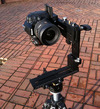
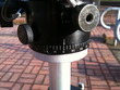
 You'll need a way to take several of these images in a circle, pivoted about the lens.  We want to pivot around the lens so that there will be minimum paralax distortion.  With a very wide lens, moving the slightest bit can make the images very different and not align for our HDRI later.  To do this, I bought a Manfrotto 303SPH QTVR Spherical Panoramic Pro Head (Black)  that we can mount to any tripod. This head can swivel almost 360 degrees.  A step down from this is the Manfrotto 303PLUS QTVR Precision Panoramic Pro Head (Black)  which doesn't allow 360 degrees of swivel, but with the 4.5 fish eye lens, I found you don't really need to tilt up or down to get the sky and ground, you'll get it by just panning the head around.

Once you got all that, time to shoot your panoramic location.  You'll want to set up the head so that the center of the lens is floating right over the center of the mount.  Now in theory, this lens can take a 180 degree image so you only need front and back right?  Wrong. You'll want some overlap so take 3 sets of images for our panorama each 120 degrees apart. 0, 120, and 240. That will give us the coverage we need to stitch up the image later. 

  • Alignment

Just like the mirrored ball, I like to shoot the the image back at the direction of the plate camera. Set up the tripod so that 120 degrees at pointing towards the original camera position.  Then rotate back to 0 and start taking your mutiple exposures.  Once 0 is taken, rotate to 120, and again to 240 degrees.  When we stitch this all together, the 120 position will be in the center of the image and the seam of the image will be at the back where 0 and 240 blend. 

  •  Don't Worry About...

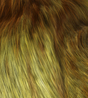
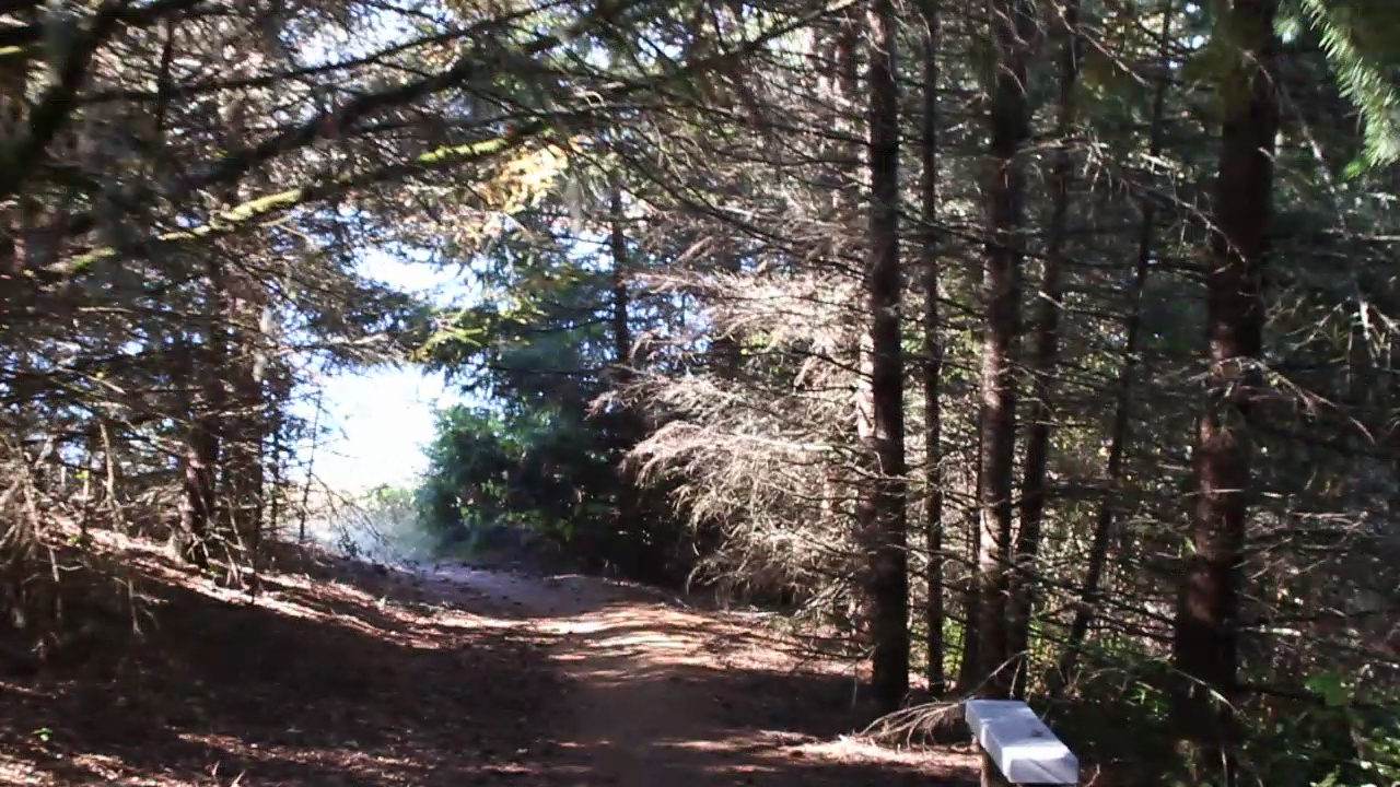
People walking through  your images.  Especially on a live action set.  There is no time on set to wait for perfect conditions.  By the time you blend all your exposures together that person will disapear. Check out the Forest_Ball.hdr image. You can see me taking the photos, and a ghost in a yellow shirt on the right side.

Processing The Panoramic Images

To build the paroramic from your images, you'll need to go through three steps. 1. Make the HDR images (just like for the mirrored ball).  2. Transform the round fish-eye images to square latitude/logitude images, and  3. Stitch it all back together in a cylindrical panoramic image.

  • Merge to HDR

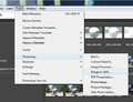
Like we talked about before, Adobe Bridge can easily take a set of different exposures and make an HDR out of them. Grab a set, and go to the menu under Tools/Photoshop/Merge to HDR.  Do this for each of your 0, 120 and 240 degree images and save them out.

  • Transform to Lat/Long

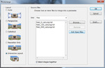
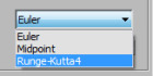
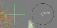
Photoshop doesn't have any tool for distorting a fish-eye lens to a Lat/Long image.  There are some programs that I investigated, but they all cost money.  I like free.  So to do this, grab a copy of HDR Shop 1.0 Open up each image inside HDRshop and go to menu Image/Panorama/Panoramic Transformations.  We set the source image to Mirrored Ball Closeup and the Destination Image to Latitude/Longitude. Then set the resolution in height to something close to the original height. 

  •  Stitch It Together Using Photomerge

OK. You now have three square images that you have to stitch back together.  Go back and open the three Lat/Long images in Photoshop.  From here, you can stitch them together with Menu-Automate/Photomerge using the "Interactive Layout" option. This next window will place all three images into an area where you can re-arrange them how you want. Once you have something that looks ok, press OK and it will make a layered Photoshop file with each layer having an automatically created mask.  Next, I adjusted the exposure of one of the images, 
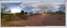
and you can make changes to the masks also.  As you can see with my image on the right, when they stiched up, each one was a little lower than the next.  This tells me that my tripod was not totally level when I took my pictures.  I finallized my image by collapsing it all ot one layer, and rotating it a few degrees so the horizon was back to being level.  For the seam in the back, you can do a quick offset and a clone stamp, or just leave it alone.

 This topic is huge and I can only cover so much in this first post.  Next week, I'll finish this off by talking about how I use HDR images within my vRay workflow and how to customize your HDR images so that you can tweak the final render to exactly what you want.  Keep in mind that HDR images are just a tool for you to make great looking CG. For now here are two HDRI's and a background plate that I've posted in my download section.

Park_Panorama.hdr          Forest_Ball.hdr          Forest_Plate.jpg

If your looking for a cheap mirrored ball you can get one here at Amazon.com. It's only like 7$!

Monday
Feb212011

Video - Spring Simulations with the Flex Modifier

Hey everybody, I decided that I would try doing some video blog entries on some of the topics I've been going over.  In this first one, Im going over the stuff I talked about with spring simulations.  I was tired when I recorded this so cut me some slack.  I'm keeping these quick and dirty, designed to just get you going with a concept or feature, not hold your hand the whole way through.

The original posted article on spring simulations with Flex is posted here.

Wednesday
Feb022011

Spring Simulations with the Flex Modifier

Ever wish you could create a soft body simulation on your mesh to bounce it around?  3ds max has had this ability for many years now, but it's tricky to set up and not very obvious that it can be done  at all. (This feature could use a re-vamp in an upcoming release.)  I pull this trick out whenever I can, so I thought I'd go over it for all my readers. It's called the Flex modifier, and it can do more than you realize.

A Breif History of Flex

The flex modifier, originally debuted in 1999 within 3D Studio Max R3.  I'm pretty sure Peter Watje based it on a tool within Softimage 3d called quick stretch. (The original Softimage, not XSI) The basic flex modifier is cool, but the results are less than realistic.  In a later release, Peter added the ability for flex to use springs connected between each vertex.  With enough springs in place, meshes will try and hold their shape and jiggle with motion applied to them.  

Making Flex into a Simulation Environment

So we're about to deal with a real-time spring system.  Springs can do what we call "Explode".  This means the math goes wrong and the vertices fly off into infinite space. Also, if you accidentally set up a couple thousand springs, your system will just come to a halt. So here are the setup rules to make a real time modifier more like a "system" for calculating the results...

  1. Save Often- Just save versions after each step you take.
  2. Use a Low Resolution Mesh- Work with springs on simple geometry, not your render mesh.  Later, use the Skin Wrap modifier to have your render mesh follow the spring mesh.
  3. Cache your Springs- Use a cache modifier on top of the Flex modifier to make playback real-time.  This is really helpful.

Setting Up the Spring Simulation

Ok, I did this the other day on a real project, but I can't show that right now so yes, I'm gonna do it on a teapot, don't gimme shit for it.  I would do it on an elephants trunk or something like that... wait a sec, I will do it on an elephant trunk!  (Mom always said, a real world example is better than a teapot example.)

OK, Lets start with this elephants head. (this elephant model is probably from 1999 too!) I'lll create a simple mesh model to represent the elephants trunk.  The detail here is important.  I start with a simple model, and if the simulation collapses or looks funky, I'll go all the way back to the beginning and add more mesh, and re make all my springs. (I did that at the end of this tutorial.)  First, lets disable the old method of Flex by turning off Chase Springs and Use Weights. Next, let's choose a simulation method.  

There are 3 different sim types. I couldn't tell you the difference.  I do know that they get better and slower from top to bottom.  With that said, set it to Runge-Kutta4 - the slowest and the most stable. (Slow is relative.  in this example, it still gives me real time feedback.)

OK. Before we go making the springs, lets decide which vertices will be held in place and which will be free to be controlled by Flex.  Go right below the Flex modifier and add a Poly Select modifier.  Select the verts that you want to be free and leave the hold verts un-selected.  By using the select modifier we can utilize the soft selection feature so that the effect has a nice falloff.  Turn of soft selection and set your falloff.

About the Spring Types

Now that we know which verts will be free and which will be held, lets set up the springs.  Go to Weights and Springs sub-object. Open advanced rollout and turn on Show Springs. Now, there are 2 types of springs.  One holds the verts together by Edge Lengths.  These keep the edge length correct over the life of the sim. The other holds verts together that are not connected by edges.  These are called Hold Shape Springs. I try to set up only as many springs as I need for the effect to work.

 Making the Springs

Bad SpringsTo make a spring, you have to select 2 or more vertices, decide which spring type you are adding in the options dialog, and press the Add Spring button. The options dialog has a radius "filter".  By setting the radius, it will NOT make springs that are a certain distance from each other.  This is useful when adding a lot of springs at once, but I try to be specific when adding springs.  I first select ALL the vertices and set the dialog to Edge Length springs with a high radius.  Then close the dialog and press Add Springs.  This will make blue springs on top of all the polygons edges.Good Springs (In new releases, you cannot see these springs due to some weird bug.)  After that, open the dialog again and choose shape springs to selected and then start adding shape springs.  These are the more important springs anyway. You can select all your verts and try to use the radius to apply springs, but it might look something like the image to the left. If you select 2 "rings" of your mesh at a time and add springs carefully, it will look more like the one on the right. (NOTE: It's easy to over do the amount of springs. Deleting springs is hard to do since you have to select the 2 verts that represent the spring, don't be upset about it deleting all the springs and starting over.)

When making your shape springs, you dont want to over do it.  Too many springs can make it unstable.  Also each spring sets up a constraint. Keep that in mind.  If you do try to use the radius to filter the amount of springs, use the tape measure to measure the distance between the verts to know what you will get after adding springs.  

Working with the Settings

In the rollout called "Simple Soft Bodies" there is 3 controls.  A button that adds springs without controlling where, and a Stretch and Stiffness parameter.  I don't recommend using the Create Simple Soft Body action. (Go ahead and try it to see what it does.) However, the other parameters still control the custom springs you make.  Lets take a look at my first animation and see how we can make it better.

You know we can make it better?  Take more than 20 seconds to animate that elephant head.  What the hell Ruff?  You can't even rig up a damn elephant head for this tutorial? Nope. 6 rotation keys is all you get.  Anyway, the flex is a bit floaty huh? Looks more like liquid in outer space.  We need the springs to be a lot stiffer.  Turn the Stiffness parameter up to 10.  Now let's take another look.

Better, but the top has too few springs to hold all this motion. It's twisting too much and doesn't look right. 

Lets add some extra long springs to hold the upper part in place.  To do this, instead of adding springs just between connected verts, we can select a larger span of verts and add a few more springs.  This will result in a stiffer area at the top of the trunk. Now lets see the results of this. (NOTE: The image to the left has an overlay mode to show the extra springs added in light pink. See how they span more than one edge now.)


Looking good.  In my case here, I see the trunk folding in on itself. You can add springs to any set of vertices to hold things in place.  The tip of the trunk flies around too much.  I'lll create a couple new springs from the top all the way down to the tip.  These springs will hold the overall shape in place without being too rigid.  

Now lets see the result on the real mesh. Skin wrap the mesh with the spring mesh.  I went back and added 2x more verts to the base spring mesh, then I redid the spring setup since the vertex count changed.  

I then made the animation more sever, so I could show you adding a deflector to the springs.  I used a scaled out sphere deflector to simulate collision with the right tusk.  Now don't go trying to use the fucking UDeflector and picking all kinds of hi res meshes for it to collide with.  That will lock up your machine for sure.  Just because you can do something in 3dsmax, it doesn't mean you should do it.


 So yeah, thats it.  Now I'm not saying my elephant looks perfect, but you get the idea.  Animate your point cache amount to even cross dissolve different simulations.  Oh, and finally, stay away from the Enable Advanced Springs option. (If you want to see a vertex explosion, fiddle with those numbers a bunch.)

Monday
Jan312011

The Secrets of Hiding Vertices

The feature of hiding and un-hiding polygon elements in under utilized in 3dsmax.  Probably because the buttons are buried so deep within editable poly. By putting a couple shortcuts in your quad menu, you can gain quick access to a very useful set of commands.

Hiding Vertices is like Freezing Polygons

I don't know if many people know this or not, but the hide un-hide tools of editable poly can be used to freeze parts of your model when working on it.  Hiding the verts, let you still see the polygons, but not see or touch the verticies.  This is helpful when using broad sculpt tools like Poly Shift or paint deformation.  I don't trust "ignore backfacing" to make my decisions for me on what to move around so I tend to hide verts I don't want to move.  I often select some verts I want to adjust and then use Hide Unselected to isolate only the verts I want to use the Poly Shift tool on.

 Hiding verts is especially important when making morph shapes.  Hide the vertices on the back of the head before sculpting a morph shape. The last thing you need to do it accidentally move some verts on the back of your characters head for one of the morphs.

Hiding Polygons to Help with Modeling

It's very useful to hide polygons to get into tight spaces.  Working with the inside of the mouth, or working in an armpit for example.  Remember to turn these polygons back on later, since they will render this way!


 Adding Them to Your Quad Menu

If you have max open right now, just do it.  You'll start to using hide and un-hide on polygons much  more often if they are in your quad menu. Open Customize/Customize User Interface dialog and go to the quad tab. I add these commands right next to regular hide and unhide in the upper right quad.  Click in the action window and press "h" on the keyboard to quickly jump to the hide commands.  You'll see one in there for "Hide (Poly)" drag that into the upper right quad.   Do that for Unhide (Poly) and Hide Unselected (Poly).  Now to make them easier to read in the quad.  Customize the name of each menu item to add the parenthesis and POLY so they are easier to recognize.  (Don't forget to save out your UI changes to your default UI file.)

The great part is when your not in an editable polygon object, they don't show up in your quad menu at all.

Wednesday
Jan192011

Skin Basics

The other night I was skinning a character and realized that some beginners might get a little lost when it comes to skinning. It started when I brought up the weight table and had to set 3 or 4 options before I could even use it.  So... here are my skin basics.

Check your bones first.  Did you name all your bones properly? Before you go assigning bones to a skin, make sure they are named. When I rig, I have bones that are meant for skinning and bones that are for the rig.   I add the suffix '_SKIN' on all my skin bones.  When picking the bones to add to the skin modifier, I just filter '*SKIN" in the select by name dialog and grab all the right bones in a split second.

The first thing I do after applying the skin modifier to a model is set up the default envelopes.  Although they seem strange and confusing I still find them very helpful for smoothing out joints. Don't jump to hand weighting verticies until your envelopes are working pretty good. If a joint creases too much, make the ends of each envelope larger and larger balancing one with the other.  You can also move envelope locations by sliding the envelopes around.  This might confuse you but keep in mind this is just the volume that will be affected by the bone.  It doesn't change where the bone pivots from.

Use excluded verts for fixing the most extreme verts.  If you go setting weights on the arm verts to get the spine bones not to affect it, you won't be able to adjust the envelopes for the elbow.  Using exclusions allows you to still weight with broad envelopes.

Bad DefaultsWhenever I skin up a character using 3dsmax's skin modifier, I always end up in the weight table.  It's a very useful tool for finalizing the skin after you've set up all your envelopes to be as good as they can be.  However, you need to set it up correctly.  When you open the weight table it's overwhelming with bone names across and vertex number down it.  Vert #1823? Which one is that? This doesn't really work by default.


To make your weight table useful again, do this.  Set the weight table to 'Selected Vertices'.  Now as you select verts you will see how much influence each bone has on them.  Next set it to 'Show Affected Bones' to only show only the bones that affect the selected vertices.  Now you can see the selected verts and how they under skin influence.  Finally, check the Use Global setting.  This adds an extra cell in the chart that can be used to adjust the entire bone column of selected verts.  The super part about this is that the effect is additive to the existing weight so each vert is tweaked a little without having to be forced to be the same value.

 Also, select the bone you want to view and it will show up in bold blue background.  If the bone doesnt show up, its becasue it has no weights assigned to those verts.  use the Abs Effect spinner to add a little, and then you can slide it up from there.   You can also use the 'Affect Sel. Verts' option to dial in weights for only certain vertices in you table.

 Questions? Post them to the Forum. Comments, post them to the Journal. Was this helpful... boring? let me that too.  I hate boring stuff.

Sunday
Jan092011

Vray Render Elements into Nuke

As a follow up to the article I wrote about render elements in After Effects, this article will go over getting render elements into The Foundry's Nuke.

I've been learning Nuke over the last few months and I have to say it's my new favorite program. (Don't worry 3dsmax, I still love you too.)  Nukes floating point core and it's node based workflow make it the best compositor for the modern day 3d artist to take his/her renderings to the next level. (In my opinion of course.)  Don't get me wrong, After Effects still has a place in the studio for simple animation and motion graphics, but for finishing your 3d renders, Nuke is the place to be. 

There a many things to consider before adding render elements into your everyday workflow.  Read this article on render elements in After Effects before making that decision. You also might want to look over this article about linear workflow too.

Nuke and Render Elements

Drag all of your non gamma corrected, 16 bit EXR render elements into Nuke.  Merge them all together and set the merge node to Plus.  Nuke does a great job at handling different color spaces for images, and when dragging in EXR's, they will be set to linear by default. 

Nuke applies a color lookup in the viewport not at the image level, so our additive math for our render elements will be correct once we add all the elements together.  (If it looks washed out, your renders probably have gamma baked into them from 3dsmax.  Check your output gamma is set to 1.0 not 2.2) If you want to play with the viewport color lookup, grab the viewport gain or gamma sliders and play with them.  Keep in mind that this will not change the output of your images saved from Nuke.  This is just an adjustment  to your display.

Alpha

After you add together all the elements, the alpha will be wrong again.  Probably because we are adding something that isn't pure black to begin with.   (My image has a gray alpha through the windows.) Drag in your background node and add another Merge node in Nuke.  Set this one to Matte.  Pull the elements into the A channel and pull the background into the B channel.  If you do notice something through the Alpha it will probably look wrong.  The easiest way to fix this is to grab the mask channel from the new Merge node and hook it up to any one of the original render elements.  This will then get the alpha from that single node, without being added up. 

Grading the Elements

That's pretty much it.  You now can add nodes to each of the separate elements and adjust the look of your final image. If you read my article about render elements and After Effects, you will remember that I cranked the gain on the reflection element and the image started to look chunky.  You can see here that when I put a Grade node on the reflection element and turn up the gain, I get better results. (NOTE: my image is grainy due to lack of samples in my render, not from being processed in 8 bit like After Effects does.)

This is just the beginning. Nuke has many other tools for working with 3d renders.  I hope to cover more of them in later posts.

Tuesday
Jan042011

Vray Elements in After Effects

Although I've known about render elements since their inception back in 3dsmax 4, I've only really been working with split out render elements for a couple years or so.  


The idea seems like a dream right?  Render out your scene into different elements and give control of different portions of the scene so that you can develop that final "look" at the compositing phase?  However, as I looked into the idea at my own studio, it's not that simple.  This is a history of my adventure of adapting render elements into my own workflow.

The Gamma Issue

The first question for me as a technical director is "Can I really put them back together properly?"  I've met so many people who tried at one point, but got frustrated and gave up.  Its a hassle and a bit of an enigma to get all the render elements back together properly.  One of the main problems for me was that you can't put render elements back together if they have gamma applied to them.  I had already let gamma into my life.   I was still often giving compositors an 8bit image saved with 2.2 gammed from 3dsmax.  So for render elements to work, I need to save out files without gamma applied.

Linear Workflow

Now that your saving images out of max without gamma, you don't want to save 8 bit files since the blacks will get crunchy when you gamma them up in composite. So you need to save your files as EXR's in 16 bit space for render elements to work.  You also need to make sure no Gamma is applied to them.  Read this post on Linear Workflow for more on that process.  

Storage Considerations

With the workflow figured out, you are now saving larger files than you would on a old school 8 bit workflow.  Also, since your splitting this into 5-6 render element sequences, your now saving more of these larger images. Make sure your studio IT guy knows you just significantly increased the storage need of your project by many times

Composite Performance

So now you got all those images saved on your network and you figured out how to put them back together in composite, but how much does this slow down your compositing process?  Well if you are your own compositor, no problem.  You know the benefits, and probably won't mind the fact that your now pulling do 5-6 plates instead of one.  You have to consider if the speed hit is worth it.  You should always have the original render so the compositor can skip putting the elements back together at all.  (Comping one image is faster than comping 5-6.)  I mean, If the compositor doesn't want to put them back together, and the director doesn't know he can ask to affect each element, why the hell are you saving them in the first place right? Also, if people aren't trained to work with them, they might put them back together wrong and not even know it.  Finally, to really get them to work right in After Effects, you'll probably have to start working in 16 bpc mode.  (Many plugins in AE don't work in 16 bit)

After all these considerations, it's really up to you and the people around you to decide if you want to integrate it into your workflow.  It's best to practice it a few times before throwing it into a studios production pipeline.  If you do decide to try it out, I'll go over the way that I've figured out how to save them out properly and how to put them back together in After Effects so that you can have more flexability in your composite process.

Setting up the Elements in After Effects

I don't claim to be any expert on this by far, so try to cut me some slack.  I'll go over how I started working with render elements specifically in After Effects CS3.  I'm using this attic scene as my example.  It's a little short on refraction and specular highlights, but there are there, and they end up looking correct in the end.


Global Illumination, Lighting, Reflection, Refraction, and Specular.

I use just these five elements. Add Global Illumination, Lighting, Reflection, Refraction and Specular as your elements.  It's like using the primary channels out of Vray.  You can break up the GI into diffuse and multiply Raw GI, and the Lighting can be created from Raw Lighting and Shadows, but I just never went that deep yet. (After writing this post, I'll probably get back to it and see if I can get it working with all those channels as well. The bottom line is that this is an easy setup, so call me a cheater. 

Sub Surface Scattering

I've noticed that if you use the SSS 2 shader in your renderings, you need to add that as another element.  Also, it doesn't add up with the others so It won't blend back in. It will just lay over the final result.

I usually turn off the Vray frame buffer since I've had issues with the elements being saved out if that is on.  I use RPManager and Dealine 4 for all my rendering and with the Vray frame buffer on, I've had problems getting the render elements to save out properly.

Bring them into After Effects

I'm showing this all in CS3.  I'm working with Nuke more often and hope to detail my experience there too in a later post. Load your five elements into AE.  As I did this, I ran into something that happens often in After Effects.  Long file names.  AE doesn't handle the long filenames that can be generated with working with elements.  So learn from this and give your elements nice short names. Otherwise, you can't tell them apart.

Before "Preserve RGB"Next make a comp for all the elements and all the modes to Add.  With addition It doesn't matter what the order is.  In the image to the left I've done that and laid the original result over the top to see if it's working right.  It's not. The lower half if the original, the upper half is the added elements.  The problem is the added gamma. After Effects is interpreting the images as linear and adding gamma internally.  Adding Final GammaSo now when the are added back up, the math is just wrong.  The way to fix this is to right click on the source footage and change the way it's interpreted.  Set the interpretation to preserve the original RGB color.  Once this is done, your image should now look very dark.  Now that the elements are added back together we can apply the correct gamma once.  (And only once, not 5 times.)  Add an adjustment layer to the comp and add an exposure effect to the adjustment layer.  Set the gamma to 2.2 and the image should look like the original.

 Dealing with Alpha

Next the alpha needs to be dealt with. The resulting added render elements always seem to have a weird alpha so I always add back the original alpha. One of the first issues is if your transparent shaders aren't setup properly. If your using Vray, set the refraction "Affect Channels" dropdown to All channels.

Alpha Problem


 Pre-comp everything into a new composition.  I've added a background image below my comp to show the alpha problem.  The right side shows the original image, and the left shows the elements resulting alpha.  So I add add one of the original elements back on top, and grab it's alpha using track matte.  Note that my ribbed glass will never refract the background, just show it through with the proper transparency. 


When this is all said and done, the alpha will be right and the image will look much like it did as a straight render. See this final screenshot.

Final Composition

OK, remember why we were trying to get here in the first place?  So we could tweak each element right?  So lets do that. 8 bit Failing When AdjustedLets take the reflection element and turn up it's exposure for example.  Select that element in the element pre-comp and add >Color Correct>Exposure.  In my example, I cranked the exposure up to 5.  This boosts the reflection element very high, but not unreasonable.  However, since After Effects is in 8 bpc (B-its P-er C-hannel) you can see that the image is now getting crushed.

So, now we need to switch the comp to 16 bpc.  You can do that by holding ALT while clicking the 8bpc under the project window.  Switch it to 16 bpc and everything should go back to normal.  But note that were now comping at 16 bit and AE might be a bit slower than before.  This is only a result of cranking on the exposure so hard.  You can avoid this by doubling up the reflection element instead of cranking it with exposure. Keep in mind that many plugins don't work in 16 bit mode in after effects.

 That's about it for after effects.  I'm curious how CS5 has changed this workflow, but we haven't pulled the trigger on upgrading to CS5 just yet.  I'm glad because I've been investigating other compositors like Fusion and Nuke.  I'm really loving how Nuke works and I'll follow this article up with a nuke one if people are interested in it.


Wednesday
Dec222010

The Missing 3dsmax Brush Cursor

Have you ever had your Hair and Fur tool brush disappear in 3dsmax? What about the Poly Shift tool? Has that ever gone missing on you?  It was there one minute, but now it's gone.  

I've had this happen a few times.  For me it first started with the Hair and Fur modifier, but it's true of the Poly Shift tool also.  I'd be distorting some mesh and then I go off and do some other stuff. I come back and my circle cursor is gone.  Im in the tool mode, but I don't see my cursor brush?!  Anywhere!  Shit, Must be the graphics card right?  Maybe restart 3dsmax.  Load the file again.  Go to tool brush mode.  Fuck! It's still missing, whats wrong, maybe I should reboot, maybe I ran out of memory? Is it file related....STOP!

The Problem

 Nothing is wrong with your machine. Don't reinstall anything or update your graphics drivers.  Just first check your layer manager.  If the "current" layer (The checked one) is hidden, then the brush cursor is hidden inside this hidden layer.  Simply unhide the layer and try the tool again.  Most likely the hidden layer was the problem.  If it's not, sorry, I can't help.  Keep Googling.

  I love seeing how many people have found my post on fixing the corrupted 3dsmax menu file so I hope people will find this post helpful too.

Wednesday
Dec152010

Linear Workflow with Vray in 3dsmax

These days, most shops are using a linear workflow for lighting and rendering computer graphics.  If you don't know what that means, read on.  If you do know, and want to know more about how to do it specifically in 3dsmax, read on as well.

Why use a linear workflow?

First thing about linear workflow is that It can actually make your CG look better and more realistic.  Do I really need to say anymore? If that doesn't convince you, the second reason is so you can composite your images correctly . (Especially when using render elements.) Also, it gives you more control to re-expose the final without having to re-render all your CG.  And finally, many SLR cameras and Digital cameras are now supporting linear images so it makes sense to keep in linear all throughout the pipeline.

A bit on Gamma

Lets start with an example of taking a photo on a digital camera.  You take a picture, you look at it, it looks right.  However, you should know that the camera encoded a 2.2 gamma curve into the image already.  Why, because they are taking into account the display of this image on a monitor. A monitor or TV is not a linear device.  So the camera maker applies a gamma curve to the image to compensate.  A gamma encoded curve looks something like this. The red curve shows how a monitor handles the display of the image. Notice the green line which is 2.2 gamma.  It's directly opposite to the monitor display, and when they combine, we get the gray line in the middle. So gamma is about compensation.  Read more on gamma here.

 The problem comes in when you start to apply mathematics to the image. (like compositing or putting render elements back together)  Now, the mathematics are off since the original image has been bent to incorporate the gamma.  So, the solution is to work with the original linear space images, and apply gamma to the result, not the source. NOTE: Linear images look darker with high contrast until you apply the display gamma to it. TV's use a gamma of 2.2. 

The problem also comes with computer graphics generated imagery.  All of CG is essentially mathematics, and for years many of us have just delt with this.  However, now that most renderers can simulate global illumination, the problem is compounded.  Again, the solution is let the computer work in linear space, and bent only the final results.

Why we use 16 bit EXR's

So, now that we know we have to work with linear images, lets talk about how.  Bit depth is the first problem.  Many of us were using 8 bit images for years.  I swore by targas for so long, mainly cause every program handled them the same. Targa's are 8 bit images with color in a space of 0-255.  So if you save the data with only 255 levels of each R-G-B color and alpha, when you gamma the image after, the dark end of the spectrum it will be "crunchy" since there wasn't much data in there to begin with.  NOw that very little data has been stretched.  Here's where 16 bit and 32 bit images come into play.  You could use any format of storage that support 16 bit.  16 bit is plenty for me, 32 is a bit of depth overkill and makes very large images.  Then you can adjust the resulting images with gamma and even exposure changes without those blacks getting destroyed.  EXR's seem to be the popular format since it came out of ILM and has support for multiple channels.  It also has some extended compression options for per scanline and zipped scanline storage so it can be read faster. 

Does 3dsmax apply gamma?

Not by default.  3dsmax has had gamma controls in the program since the beginning, but many people don't understand why or how to use it. So what you've probably been working with and looking at is linear images that are trying to look like gamma adjusted images.  And your trying to make your CG look real? I bet your renderings always have a lot of contrast, and your probably turning up the GI to try and get detail in the blacks. 

Setting up Linear Workflow in 3dsmax

Setup 3dsmax Gamma

First, let' set up the gamma in 3dsmax.  Start at the menu bar, Customize>Preferences and go to the Gamma and LUT tab.  (LUT stand for Look Up Table. You can now use custom LUT's for different media formats like film.) Enable the gamma option and set it to 2.2 (Ignore the gray box inside the black and white box.) Set the Input gamma to 2.2.  This will compensate all your textures and backgrounds to look right in the end.  Set the Output gamma to 1.0  This means we will see all our images in max with a gamma of 2.2, but when we save them to disk, they will be linear.  While your here, check the option in Materials and Color Selectors since we want to see what were working with. That's pretty much it for max.  Now lets talk about how this applies to Vray.

Setting up Gamma for Vray

You really don't have to do anything to Vray to make it work, but you can do a couple things to make it work better.  First off, many of Vray's controls for GI and anti-aliasing are based on color thresholds. It analyzes the color difference between pixels and based on that does some raytracing stuff.  Now that we just turned on gamma of 2.2 we will start to see more noise in our blacks.  Let's let Vray know that were are in linear space and have it "Adapt" to this environment.

 Vray has it's own equivalent of exposure control called Color Mapping.  let's set the gamma to 2.2 and check the option, "Don't affect colors (adaptation only)".  This will tell Vray to work in linear space, and now our default color thresholds for anti-aliasing and GI don't need to be drastically changed.  Sometimes when Im working on a model or NOT rendering for composite, I turn off the "Don't affect colors)" which means that I'm encoding the 2.2 and when I save the file as a JPG or something, it will look right. (This easily confuses people so stay away from switching around on a job.)

Vray Frame Buffer

I tend to almost always use the Vray frame buffer.  I love that it has a toggle for looking at the image with the view gamma and without. (Not to mention the "Track Mouse while Rendering" tool in there.)  The little sRGB button will apply a 2.2 gamma to the image so you can look at it in gamma space while the rendering is still in linear space. Here is just an example of the same image with and without 2.2 gamma. Notice the sRGB button in the bottom of these images.

 This asteroid scene is show without the gamma, and with a 2.2 gamma. Try doing that to an 8 bit image.  There would hardly be any information in the deep blacks.  With a linear image, I can now see the tiny bit of GI in the asteroid darker side.

Pitfalls...

Vray'sLinear Workflow Checkbox

I'm referring to the check box in the Color Mapping controls of the Vray Renderer. Don't use this.  It's misleading.  It's used to take an older scene that was lit and rendered without gamma in mind and does an inverse correction to all the materials. Investigate it if your re-purposing an older scene.

Correctly Using Data Maps (Normal Maps)

Now that we told max to adjust every incoming texture to compensate for this monitor sillyness we have to be careful.  For example, now when you load a normal map, it will try and apply a reverse gamma curve to the map, which is not what you want.  This will make your renderings look really fucked up if they are gammed compensated. Surface normals will point the wrong way. To fix this, always set the normal map image to a predefined gamma of 1.0 when loading it.   I'm still looking for discussion about if reflection maps and other data maps should be set to 1.0.  I've tried it both ways, and unlike normals, which are direction vectors, reflection maps just reflect more or less based on gamma.  It makes a difference, but it seems fine.

Always Adopt on Open

I've also taken on the ritual of always taking on the Gamma of the scene I'm loading.  Always say yes, and you shouldn't have problems jumping from job to job scene to scene.

Hope that helps to explain some things, or at least starts the process of understanding it. Feel free to post questions since I tend to try to keep the tech explanations very simple.  I'll try post a follow up article on how to use linear EXR's in After Effects

Tuesday
Dec142010

Swapping Instanced Models inside Trackview

Have you ever hand placed a lot of instances, but then realized that you actually wanted to swap out the entire object?  This leaves you with a problem since you want to keep the placement of the original obejcts, but you also want to use a new object.  One way is to add an edit mesh to any instance and "Attach" the other mesh to it, but that's sloppy.  Here's a neat little trick many people don't know.  You can copy and paste modifiers and base meshes in the track view.

 In this example, I hand placed 720 small sphere as "light bulbs".  But the sphere's aren't cutting it for the realism I want.  So, I need to replace all the sphere's with my new light bulb object on the right.

 First, to help things out, use the align tool and align the bulb to one of the spheres,  taking it's rotation and scale values. (Ignore position XYZ) Now if the bulb is took big, or oriented the wrong way, don't use the transform tools, use an Xform modifier or edit the mesh itself to line back up.  This will ensure that when we do replace the sphere, the bulb will be the same sale and rotation within the object space. 

Now, select on the new object and open the track view.  Navigate to the modifier or base object you want to copy.  In this case, I had an Editable Mesh.  Right click and choose "Copy" from the right bottom quad menu.  Then, select any of the instanced object, and navigate to it's base object.  In this case it was a sphere primitive.  Click on the sphere base object and right click again.  Choose "paste" from the right bottom quad menu.  Now when you get the paste dialog the first choice is to copy from the original or instance.  In this case, I don't need the original, so I'll leave it at copy.  Below is the key option.  "Replace All Instances" This will find all the instances of the sphere and replace them with my new object.

 Pretty cool huh.  You can also do this with modifiers and base objects anywhere in the track view.


Friday
Dec032010

Getting Good Fur from 3ds max

OK, let's all admit that we're a little disapointed with the Hair and Fur system in 3ds max.  However, if you can't afford a better solution like Hair Farm, there is still hope.  Although the system is max has it's issues, you can still get some decent fur renderings out of it.  Here's a few fur tips that I remember doing before we got Hair-Farm.
            
These are a few examples of Fur that I've done with max's hair and fur system. (The are close up's. I didn't get approval to show the characters.)
Styling Fur
  1. When you first apply hair and fur, it might be very long compared to your model.  (I have no idea how the hell it gets it's scale.  It seems to be arbitrary to me.) Don't try to use the sacle setting to make it smaller. Use the style tools to get it smaller, then use the scale and cut spinners to tweak it when finishing.
  2. First thing I usually do is go into style mode and get the length right.  To do this you will have to first turn off DISTANCE FADE so that you can do an overall scale without having the brush fall-off from the center. Then zoom way out and try to eye it up from afar.
  3. Next, it the comb tool  This is great for animal fur.  Yes, I said it was great and it is. Use the transform brush to quickly brush the hair in a general direction.  Then press the comb button. Ta da! Great for making hair lie down along your surface very fast.
  4. Frizz is wavy and useful, Kink is some weird noise pattern that scatters the hair vertices. I try to avoid it. It's not very realistic.
  5. There is no way to make perfect little loops or helix's. Get over it. You can try to style it, but that might make you insane.

Lighting and Rendering

  1. Don't try to use geometry. it's stupid. Take advantage of the buffer renderer as much as possible.
  2. I also didn't find mental ray primitive option a solution.  Mental ray is a raytracer so to get smooth hair from frame to frame, you had to turn up the anti aliasing so high, I found it looked just like the buffer hair anyway.
  3. Turn off the vray frame buffer.  Hair and Fur are render effects and are computed into the max frame buffer. You won't see then in the vray frame buffer.
  4. Switch back to shadow maps and get over it. (Or render separate passes to use Vray soft shadows) 
  5. Keep the light cones tight around your hair since it's now resolution dependent.  (thats what she said?) Start with at least 1k hair maps. Im sure you'll need them to be 2k if your animating.
  6. Start to turn up the total number of hair, but render aas you go. (And save before rendering)
  7. Watch for missing buckets. If this happens, you can make the buckets smaller. in the Render Effects dialog.
  8. Use thickness to fill between hairs.  If you can't throw any more hairs at it, thicken the hairs.  Better yet, make sure the surface underneath has a hair looking texture on it. That will keep your render time down too.

 Material

  1. Turn down the shininess right away.  Its supposedly for simulating real hair, but often it looks very artificial.  
  2. Maker sure to set the colors for the tip and root to white when using texture maps.  These color swatches are multiplicative and anything other than white will make your map look wrong.
  3. Look out for the Hue variation amount.  It's defaulted at 10% and that'd high.  It will vary the hue of the hair and can start you off with purple, red and brownish hairs.

Don't get me wrong.  Max's hair and fur is a pretty much a pain in the ass and really should delt with.  I'm now using Hair Farm like I mentioned above, and the difference is worlds apart. Hair farm is fast, robust and the results look very nice.  (Speed is king in look development. if you can render it fast, you can render it over and over, really working with the materials and lighting to make it look the way you want.) 


Saturday
Nov272010

Top Free Tools I Can't Do Without

OK, maybe can't do without is a bit strong, but seriously.  If you're using 3ds Max and don't know about these tools read this article. I just wanted to write about my top free scripts, but I needed to expand it to plugins also. Over the last few years, I've tried many different scripts and tools to help me in production, here are my top favorites.

Bercon Procedural Maps

The Bercon Maps are a set of procedurals for 3ds max that are superb.  The noise is so versatile, you can throw away every other noise procedural that came before.  The best part about these is they look very realistic, but have all the benefits of being procedural. (just check out the images on the website) Shane Griffith over at Autodesk should really just buy this set so we don't have to chase them down every release.  

 PEN Attribute Holder

If you've ever used the modifier in max called Attribute Holder, to store custom attributes on an object, this is an awesome version of that. This is very dear to my heart since I wrote the original "Attribute Holder" modifier that's still in max today.  This version actually does something, unlike mine. My version was a hack to an existing modifier in which I hid it's UI. The PEN Attribute holder captures applied custom attributes and saves presets as sliders that you can use to call the attributes back. I use it on all my characters hand controls, as a way to store finger poses. First I connect all the finger rotations to custom attributes on the PEN modifier. Once the data is instanced as a rotation and a custom attribute, Paul's modifier stores the values together as one preset. (If anyone wants me to explain this more, let me know.)

Blur Beta Plug-in Pack

Blur was developing shaders and procedurals for 3ds Max since it first came on the scene. Many of these are re-compiled each release and given away for free. Splutterfish now hosts them since those are the guys that originally wrote them.  Thanks guys, for recompiling these every release.

 Sub-Object Gizmo Control

This is a great tool written by Martin Breidt.  It allows any modifier transform to be linked to another 3D object.  For example,  you can use this to set up a UV Map modifier that can be rotated with separate control object. Martin has some other greats tools on his site. Check them out here.

And as always, Script Spot is a great source for finding new scripts.  Let me know if you come across something cool!

Tuesday
Nov232010

3ds Max Doesn't Start -- Unknown property: "getMenu"

Have you ever gotten and error like this?

-- Unknown property: "getMenu" in undefined


Well, I have, and it means max will not start up correctly. After many hours trying to locate the problem I found the cause. The max default .mnu file got corrupted.

Go into your user settings folder (If your not aware of this folder, max creates this for you and all your local settings are stored here.) This folder is slightly different on different operating systems.  I am running Vista (Don't ask why, but it runs fine)

User Settings Folder - C:\Users\fredr\AppData\Local\Autodesk\3dsmax\2011 - 32bit\enu\UI

Once there, simply delete your MaxStartUI.mnu.  Next time you start max, it will notice the missing file and pull one from the program files location.  I have saved my .mnu file now so that when this happens again. (And I'm sure it will...)  I'll have it ready.

Friday
Nov192010

Understanding 3ds Max's Normals


 The other day someone asked me, "I cut a poly object in half, but when i render, I get a seam. Why is that?" If you've ever tried to make something the was two individual parts, look like it was one, you've run into this problem. This can happen when destroying something or making a hidden door appear from nowhere. (See the example to the right.)  I can try to explain why. Lets first start by understanding normals, and then how 3ds Max deals with normals.

Faceted and SmoothedWhat the hell is a "normal" anyway? I can only explain it the way I understand it.  Imagine we have 3 vertices that make a polygon.  That polygon has a direction, and that direction is where each of the verticies store a normal vector. (Imagine a little arrow point out of each vert on that polygon.) Now no polygon is truly smooth. Even when you have millions of polygons, they are all made up of small flat surfaces and therefore, are never really smooth. When the renderer (viewport, scanline or ray-tracer) hits the surface, it uses the interpolated normal direction when calculating how light hits the surface.  This can make it look smooth in the render than it actually is.   This will make all the little flat polys look like they are continuous across a surface when hit with light.  However, this easily breaks down when you have very few polygons.  Try smoothing all the normals on a cube, for example.  When smoothing across very hard angles the illusion looks silly.  

3ds Max has calculated normals.  I say "calculate" because max doesn't store normal information by default.  You see, back in the early days, it was decided that max would calculate the normals on the fly, instead of having to deal with them with every step in the modifer stack.  The benefit is that max can stack many modifiers and not have to deal with normals at all, until the end result.  This is why we have something called smoothing groups.  Smoothing groups are the idea that any 2 faces can share a group, and the normals will be averaged over those 2 polygons.  Smoothing groups may seem like a mystery, but think of it as a simple puzzle. Here are the rules...

Smoothing Group Rules:

  1. Faces that are welded together can be smoothed.  Faces that are separate elements will not be smoothed. (This is why separate parts don't smooth.)
  2. Each face can be part of 32 different smoothing groups.
  3. Any polygons that share a group number will smooth across the faces, assuming they are touching. (Rule #1)

 Here's an example of smoothing groups at work.

 Notice how the #1's and #2's all smooth together, and then in the third example, the center faces with #1's and #2's all smooth together.


Select Faces

Detach Faces

Now let's deal with our example where smoothing groups break down.  Lets take a few faces and detach them to a new object.  This is where the normals start looking broken and non-smoothed again since the faces are no longer connected. 

Now, Lets fix the problem we created. Select both of the objects and add an Edit Normals modifier on top.  Now, open the normals sub-object, and select the normals on each side of the break.  Press the average "Selected" button in the Edit Normals modifier.  This will make the poly across the different object smooth together. Do this with the rest of the polygons on the objects and you now should have a smooth surface across 2 separate objects.


 And finally, the result of fixing the normals on the iPhone transformer. If you look close, you can still see something going on there, but it works enough for what I'm doing.


Thursday
Nov182010

New 3dsMax 2011 Icon

Tired of accidentally launching max 2011 when you meant to launch 2010? (Or vice-versa?)  Nothing fancy here, just a color shift to the 2011 icon and added 2011 text in the corner.  Download this new 3dsmax2011.ico file on the downloads page. Swap it out by editing the  shortcut properties on your desktop.

Sunday
Nov142010

2011 - Classic Max Interface


I just started converting the studio over to max 2011. (Mainly for the EXR improvements, thats pretty much it.) Many people including myself are frustrated with Autodesk's lack of respect for the user interface in 3dsmax.

 When I worked back at Autodesk, I moved the "Make Preview" item from the rendering menu, to the animation menu, and I got so much shit for it.  I learned my lesson on that.  (I thought it made more logical sense to refer to it as an animation action then a rendering one.) At the same time, I also assigned a ton of default hotkeys.  Before Max 5, there really weren't many hotkeys.  One of my first actions as product designer was to assign default hotkeys.   The one that caused some controversy was the "W" key.  it was originally maximize viewport, but I wanted to make it easy for Maya users to jump into Max and to do this, I would have to change it.  I went for it and re-assigned maximize viewport to "ALT+W"  I did get a little flack for it, but I didn't regret the decision.  People quickly adjusted and I unified some hotkeys between Max and Maya, making them similar when it came to basic hotkeys.

The user interface can be improved, but most of the choices we're seeing are not being considered improvements to the user base. They're just changes. 

The Icons

Icons had color, now they are monochrome.  This makes them hard to decipher, end of story. I put them back to the classic icons, and kept the newer ones. Download the classic icons for 2011 here.

The Menu

The Idea that the new large button in the upper left corner will replace the old file menu is silly. (I couldn't find a what to put save increment in it?) Want it back, it's still there, just drag it back onto the main menu bar.  I also dropped Save Increment into the file menu. Download this version of the max menus here.

The Colors

No need for a download here.  Just load up the lighter colors that come with max. The attempt to do darker colors came from the discreet tools like flame and Inferno, but the max conversion just isn't as elegant.

Saturday
Nov132010

Particle Flow - A History and Practical Applications

Wow, that title sounds like a fancy Siggraph paper...

One of my favorite parts of 3ds Max is the Particle Flow system.  Maybe because I had a hand in designing it, or maybe because Oleg over at Orbaz Technologies is brilliant? 

The year was 2001...

3dsmax was in desperate need of a new particle system.  Autodesk,or was it Kinetix, no wait, Autodesk Multimedia, no wait, discreet?  Shit, I don't remember. (And I don't care anymore.) Anyway, they hired the right man for the job.  Oleg Bayborodin. Oleg had had some previous experience with particles and wanted to take on building an event driven particle system.

Here's where I come in.  I designed the entire sub-system architecture! (Wow I can't even lie very well.)  Just kidding.  Oleg designed and built the whole whole thing.  My job, was to consider the user experience, assist in UI design and provide use cases for how the tool was going to be used.

Particle Flow Design Analogy

I used to be love experimenting with electronics as a kid, and when I saw the design of particle flow, It reminded of electronic schematics.  (I built my share of black boxes with blinking LED's in them, pretending they were "bombs", or hi tech security devices.) So I ran with that as an analogy.  Recently I came across some of the original designs and images that inspired the particle flow UI design.

Schematic Inspirations


Early design


We then started to apply it to these particle events, which were more like integrated circuits than transistors and resistors. We used a simple flow chart tool to design them and that started to look like this.


From there, the design started to look more like what we see today.

Final design

 Unfortunately, since we were building a new core system from scratch, some of the use cases couldn't be achieved with this first incarnation of the system.  We only time to do so many operators and tests. Bummer. But everyone figured we'd get to a second round of particle operators in the next release of max, so no big deal.  However, Autodesk did some restructuring and a few engineers were let go and we were left with a great core, and no one to build on it.

Luckily, Oleg went on to create a series of Particle Flow extension packs and I hope he's making a good living off them. So let's look at using Particle Flow in production.

Particle Wheat Field for Tetra Pak

Here's a fun commercial. Let's go over some of the ways particle flow was used in this spot for Tetra Pak.  First, let's take a look at the spot.


I was asked to create a field of wheat that could be cut down, sucked up into the air, and re-grown. It seems so simple to me now, but when you think about it, that's a pretty tall order.  I went directly to a particle system due to the overall number of wheat stalks. (Imagine animating this by hand!)  

 At first I create a 3d wheat stalk and instanced it as particles.  This was a great start, but it looked very fake and CG, and since I modeled each wheat grain (Or whatever you call individual wheats) the geometry was pretty heavy.  Other issues were having the wheat grow, get cut and re-grow.  As I tried an animated CG wheat stalk as an animated instance mesh particle, but this brought  the system to a crawl. I quickly realized that a "card" system would work much better.  Also, Bent has many stop motion animators so we thought we would lean on our down shooter and an animator.  This worked great.  We now had a sequence of animated paper wheat stalks that could grow by simply swapping out the material per frame.  (did you get all that?)


Blowing in the wind was also a tricky thing at first.  I thought I might be able to slap a bend modifier on the card and have the particles randomize the animation per particle, but thatwon't work.  They won't  move like a field of wheat. Instead, each particle would have a randomizing bend animation. Instead, I had to use lock\bond, part of particle flow box 1. (Now part of 3ds Max) This worked really good. The stalked waved from the base, not exactly what I wanted, but it worked good enough.


Wheat stalk shadows were my next problem.  Since I was now using cards with opacity, my shadows were shadows of the cards, not the alpha images.  They only way to deal with this was brute force.  I had to switch over to ray traced shadows. At this time I split up the wheat field into 4 sections. This allowed me to render each section and not blow out my render farm memory.

From here, the cutting of wheat was a simple event, along with growing the wheat back.  Much of the work was in editing the sequence of images on the cards. The final system looked like this.


The Falling Bread

The second problem I ran into on this job was when the bread falls on Bob. (That's the bunny's name)  At first I tried to use max's embedded game dynamics system, reactor.  I knew this would fail, but I always give things a good try first.  It did fail.  Terribly. Although I did get a pile of objects to land on him, they jiggled and chattered and would never settle. Not just settle in a way i like, but settle at all.

Particle Flow Box #2 had just been released.  This new extension pack for particle flow allows you to take particles into a dynamic event where simulations can be computed. Particle Flow Box#2 uses Nvidia's PhysX dynamics system, which proved to be very usable for production animation. (PhysX dynamics are now available for 3ds Max 2011 as an extension pack for subscription users.)

With Box#2 installed, making the bread drop was so easy. There really isn't much to say about it. Box #2 has a default system that drops things so I was able to finish the simulation in a day or so, tweaking some bounce and friction settings.  I used a small tube on the ground to contain the bread so that the it would "pile up" a bit around the character. 

Schooling Fish

A shot of the Sardine ModelTo show just one more example of how flexible Particle Flow really is, here's a spot I worked on where I used Particle Flow to control a school of sardines for the Monterey Aquarium. I should mention that I only worked on the sardines in the first spot, and all of  these spots were done by Fashion Buddha.


Thursday
Nov112010

Customizing 3DS Max Start Up Settings

How many times a day do you start a new scene in 3ds max and switch the renderer to Vray and set up all your default settings?  Are you ever in the middle of animating, only to realize that you forgot to switch your framerate to 24 fps?  I have the answer to those problems and more.

One of the simplest and most useful things about 3dsmax is a secret file called maxstart.max.  It doesn't exist when the program is installed, but all you have to do is create it in your default \Scenes folder, and when max is started or reset, this file is loaded. So start up 3ds max and lets set some good startup defaults going.


Set the default Framerate

 I don't know about you, but almost everything I do is at 24 frames per second. (Maybe cause we all want to believe that everything we do is a little film.) Every once in a while I do something for PAL in which it becomes 25 fps, but 24 is my default 90% of the time.  Open the time configuration dialog and set your framerate. 


Set your default Animation Range

You'll notice that when you switch from 30 to 24 fps, the time range with shorten to 80 frames.  You might as well set this to what you want also. I want to start with 6 seconds of time. (24*6 = 144 frames)

Set Your default Gamma

I'll do a whole entry on gamma at another time. I mention this now since my render settings will be taking this into account in the next section.

  • Gamma = 2.2
  • Affect Color Selectors = True (Duh)
  • Affect Material Editor= True (Of course)
  • Input Gamma = 2.2 (To compensate for images comming in as textures)
  • Output Gamma = 1.0 (Because I want my images linear space for compositing)


Set up your default Renderer

Now I'm sure your using something other than the max renderer (I love you baby. We went threw some good times together back in the day, but I outgrew you years ago.) so go ahead and set that up, along with any default settings you like.  Here's my defaults and a brief explanation of why. If you have any questions, hit me up in the forum section.

  • Enable Built in Frame Buffer (Cause tracking the mouse while rendering is awesome)
  • GI Environment = On (Cause my background image is NEVER my GI source)
  • GI Environment Color = White (I don't like to put any color in without thinking about it)
  • GI Environment Multiplier = .25 (I use a gamma of 2.2 and therefore don't need the GI so high)
  • Color Mapping Gamma = 2.2
  • Color Mapping Don't Affect Colors = True (This allows Vray to consider 2.2 gamma correctly, without adding it to the final image. Press the sRGB button when the frame buffer comes up to see the image with and without 2.2 gamma)
  • GI = On
  • Ambient Occlusion = On (Hell why not, adds a little extra detail)
  • Irradiance Map, Custom, -3 -3  (Because when you start working on a scene, you don't need to run through 3 pre-pass stages to see what the hells going on. Save yourself some time would ya.)

 Set up your default 3D Scene

I like to always start with a matte shadow ground plane so shadows have someplace to land. Also, don't leave your background completely black.  It's very mis-leading when rendering models.  I like to throw in some kind of gradient or something so that's lighter, but not completely white either.  I find a light warm color works pretty good.

Set up your Material Editor

Finally, if set up your material editor to have some Vray materials to work with.  For this, I'll show you a little trick so that the reset material editor slot command fills it with Vray materials instead of max materials.

Go to Customize>Customize User Interface>Menus,  From there, navigate the right drop down to Medit - Utilities.  This shows you the menu for the material editor's Utilities menu. Right click on the action item "Reset Material Editor Slots" and click "Edit Macro Script" This brings up a maxscript file that has 3 macros in it.  We will edit the reset macro so that it resets the slots.  Find this line.

meditMaterials[i] = defaultMtl name:(defaultMtl.localizedName + #'_' as string + i as string)

and replace the defaultMtl with VRayMtl.  Press CTRL+S to save that script and CTRL+E to evaluate it.  Now just go to the material editor and run the rest command under the utilities menu.

Ta Da!  Now save that file out as maxstart.max in your scenes folder and every time you start up, that will be your start up scene. See the Download section for my example maxstart.max file.

(Note: If your having a problem getting the maxstart.max file to load, check to make sure that it's in your default scenes folder.  Go to customize>Configure User Paths to figure out where your scenes folder is pointed to.)